MARCEE Minnesota Area R/C Electric Minnesota Area R/C Electric Flight Enthusiasts
Setting Up a PC's Power supply to use with your Dc/DC battery charger
By Pat Harvey
Most of us have several battery chargers for our NiCad packs. Most of these chargers only operate on 12 volt DC inputs (your car battery). This is fine as long as you are at the flying field. This isn't so fine when you want to cycle a pack on the workbench or peak up a pack before you leave for the field (and the wife has the car). We have all had the need for a good source of 12 volt DC power, good clean power. I had a couple of simple power supplies but one of my chargers would not run on either of them.
The power supplies from old PCs will provide good clean power that will run either (as well as both concurrently) of my chargers. One charger is an Astro 110D and the other is Dymond Super Smart Charger. If you have the need - Let's get started. The basic tools you will need are a VOM, screwdrivers, soldering iron, wire cutter, pliers, drill and bits.
The first thing is to get an old PC power supply. If you have an old machine setting gathering dust that you should have thrown out, you are in luck. If you don't have one, then stop by the local PC fix-it shop. Often they will have machines that are destined for the dumpster that have perfectly good power supplies. Just offer to haul the whole thing off for them and you may have a real bargain. If you can't get one for nothing, then many shops sell used power supplies at a fair price. I've had very good luck in getting free ones.
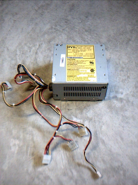
Open the PC case and take a look at the top of the power supply box. It will tell you how many amps at +12 volts are available from this power supply. It should be at least 4 amps to be of much value. A 7 or 8 amp output on +12 volts is very common and if this box is too low power you may wish to look for a different power supply. In order to take the power supply out of the case do not cut any wires, simply unplug everything. Once you have the power supply out of the PC case, you have to decide which of three basic types of power supplies you have. If the switch for the power supply is a paddle switch on the side of the power supply itself you have an older AT style power supply. If it is a push button type switch, either on the side of the power supply or on an umbilical cord them you have a newer AT style power supply. If it only has a "rocker" type switch (or no switch) it is probably an ATX style power supply. The label may in fact have "ATX" on it. An ATX style will have a plug that goes to the motherboard which has a double row of connections with 10 connections on each side. Only bother reading the section that follows that applies to your style of power supply.
Older AT Style Power Supply (the ones with the paddle switch on the side)
You are in luck. This old style power supply (PS) is much simpler to make work and generally the case is larger so you have more room to work. Plug in the power supply and turn it on. The fan should be running. Use your VOM and identify the correct color pair of wires for +12 volts. This is fairly easy. Pick a set of wires that ends in a plug with only 4 wires. This probably went to a disk drive (either hard disk or floppy). There will be 2 center wires the same color (probably black) and the outside wires will be different colors (perhaps yellow and red). Use the VOM with one probe in a center wire and one probe in an outside wire. What you will find is that the center wires equate to a negative post on a battery and the outside wires are the positive posts. With enough trial and error you can identify most of the colors. Ones that I have seen are:
Yellow +12 volts
Black Common
Red +5 volts
Orange -5 volts
Blue -12 volts
White Power good .
There will be a lot of +12 volt wires, a lot of +5 volt wires, an awful lot of "Common" wires and only one or two -12 volt or -5 volt wires. Normally there is only one "Power Good" wire.
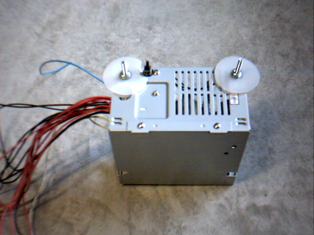
Now that you know which color is +12 volts and which is "Common" all you need to do is "design" your box. Since we plan to use this power supply as a substitute for a car battery I envision it with "Positive" and "Negative" posts, just like a battery. Pick two locations on the PS case that will allow your charger to be clipped onto without shorting out, and that you can run several wires to the inside of the PS case to those locations. Go to the local hardware store and get:
2 rubber grommets (1/4 inch center holes is fine)
2 #10 machine bolts 1 1/2 inches long (these should go through the grommets without problem)
4 nuts for the bolts
4 flat washers for the bolts
4 large (probably 1/4 inch by 2 inch diameter) nylon (or other insulating) washers with small (1/4 inch) holes in center
Now back at the shop. If you happen to have some Red Zagi tape and some Black Zagi tape then cover one side of a Nylon washer with Red and one side of another Nylon washer with Black. Trim the tape from the uncovered side with a sharp knife. Drill a 5/16 hole at each of your chosen locations. Put a rubber grommet in each hole. Next cut 3 or 4 of the +12 volt wires to length to reach the first hole. Solder these wires to the bolt (near the head). "Ring terminals" are an excellent option rather than soldering directly to the bolt but either route will work. Put a nut on the bolt and tighten it against the soldered wires. Put a metal flat washer on the bolt. Next put one of the nylon washers on the bolt. Shove the bolt through the grommet. If necessary you can trim the nylon washer a bit if it conflicts with something but leave enough of the nylon washer to be sure the wires do not contact the PS case. Put another nylon washer (the Red one if you covered one with Zagi tape) on the bolt. Put another metal flat washer on the bolt. Put another nut on the bolt and tighten it up. You now should have "Positive" battery post that is fully insulated from the PS case.
Next cut 3 or 4 of the "Common" wires to length to reach the second hole. Repeat the same process you did with the plus 12 volt wires this time using "Common" wires. Use the Black Nylon washer on this one if you covered one with Zagi tape. You now have the "Negative" post for your new PS. Now all that is left is to cut off the excess wires such that they will not short out. Put the cover back on the power supply and mark the posts as "Positive" and "Negative". You are done.
Newer AT Style Power Supply (the ones with the push button switch on the side or on a cord)
This power supply (PS) is a bit more complicated than the older ones and requires a bit more work. Not only that they tend to be smaller and there is less room to work inside the PS box.
Plug in the power supply and turn it on. The fan may be running or it may just start and then stop. Generally the following colors will identify specific functions - generally:
Yellow +12 volts
Black Common
Red +5 volts
Orange Power good
Blue -12 volts
White -5 volts
Green or Grey Power Supply � On (PS-on)
Note: "PS-on" may not exist. If it exists it will be part of the double rowed plug that went to the motherboard of the PC.
If the fan is not running consistently turn the power off and temporarily connect "Power Good" to a +5 volt line. This should cause the fan to run consistently when the PS is turned on. If the fan is still not running you should look for the "PS-on" line and connect it to a "Common" line. The PS-on line is in fact a switch to turn on (or off) the PS. Use your VOM and identify the correct color pair of wires for +12 volts. This is fairly easy. Pick a set of wires that ends in a plug with only 4 wires. This probably went to a disk drive (either hard disk or floppy). There will be 2 center wires the same color (probably black) and the outside wires will be different colors (perhaps yellow and red). Use the VOM with one probe in a center wire and one probe in an outside wire. What you will find is that the center wires equate to a negative post on a battery and the outside wires are the positive posts. With enough trial and error you can identify most of the colors. There will be a lot of +12 volt wires, a lot of +5 volt wires, an awful lot of "Common" wires and only one or two -12 volt or -5 volt wires. Normally there is only one "Power Good" and one PS-on wire.
Make the connection from "Power Good" to +5 volts a permanent connection (solder it with a bit of heat shrink).
Now that you know which color is +12 volts and which is "Common" , next you need to "design" your box. Since we plan to use this power supply as a substitute for a car battery I envision it with "Positive" and "Negative" posts, just like a battery. Pick two locations on the PS case that will allow your charger to be clipped onto without shorting out, and that you can run several wires to the inside of the PS case to those locations.
You may wish to move the PS power switch into the case if it is an "umbilical" cord type switch. I normally choose to move it into the hole that the "umbilical" cord comes out of the PS case through. This process is just a matter of unsoldering the wires, shortening them and re-soldering them. Be sure to solder the right same colored wires back onto the same lugs on the switch. You will probably need to drill a couple of mounting holes in the PS case to hold the switch and mount the switch using these holes and a screw through each.
Go to the local hardware store and get:
2 rubber grommets (1/4 inch center holes is fine)
2 #10 machine bolts 1 1/2 inches long (these should go through the grommets without problem)
4 nuts for the bolts
4 flat washers for the bolts
4 large (probably 1/4 inch by 2 inch diameter) nylon (or other insulating) washers with small (1/4 inch) holes in center
A 12 volt automotive light with a socket and wires (I use a small clearance type light with amber lens). A #1154 or #1156 bulb also works well.
Now back at the shop. If you happen to have some Red Zagi tape and some Black Zagi tape then cover one side of a Nylon washer with Red and one side of another Nylon washer with Black. Trim the tape from the uncovered side with a sharp knife. Drill a 5/16 hole at each of your chosen locations. Put a rubber grommet in each hole. Next cut 3 or 4 of the +12 volt wires to length to reach the first hole. Solder these wires to the bolt (near the head). "Ring terminals" are an excellent option rather than soldering directly to the bolt but either route will work. Put a nut on the bolt and tighten it against the soldered wires. Put a metal flat washer on the bolt. Next put one of the nylon washers on the bolt. Shove the bolt through the grommet. . If necessary you can trim the nylon washer a bit if it conflicts with something inside the PS case but leave enough of the nylon washer to be sure the wires do not contact the PS case. Put another nylon washer on the bolt (use the Red Nylon washer if you covered one with Zagi tape). Put another metal flat washer on the bolt. Put another nut on the bolt and tighten it up. You now should have "Positive" battery post that is fully insulated from the PS case.
NNext cut 3 or 4 of the "Common" wires to length to reach the second hole. Repeat the same process you did with the plus 12 volt wires this time using "Common" wires. Use the Black Nylon washer on this one if you covered one with Zagi tape. You now have the "Negative" post for your new PS.
Next choose a location on the PS case to mount the automotive light socket. Mount the light and connect it to a "Common" wire and to a +5 volt (yes plus five volts) wire. You need a small "load" on the +5 volt side of the PS in order for it to put out it's maximum voltage on the +12 volt lines. Some folks use a 1 ohm 25 watt resistor. E-zone is full of opinions on this but I find a small load works fine. If you are not getting slightly over 12 volts of output on the "posts" you can add a second light by connecting it to a "common" and a +5 volt wire.
Now all that is left is to cut off the excess wires such that they will not short out. Put the cover back on the power supply and mark the posts as "Positive" and "Negative". You are done. The automotive light will serve as an indicator light that the PS is turned on.
ATX Style Power Supply (the ones with no switch or maybe a "rocker switch" on the side of the box)
The ATX power supply will have a rather long 20 pin plug that went to the PC motherboard that has the following pin-outs:
Note that PW-OK (or PWR_OK) is the "Power Good" signal.
Conversion of an ATX style power supply proceeds just like the conversion of the newer AT style units except that you can ignore the discussion about moving the switch. Please use those guidelines (above) with this exception.