MARCEE Minnesota Area R/C Electric Minnesota Area R/C Electric Flight Enthusiasts
Getting started with LED's
By Greg
Harvey
There are many reasons to put lights on a plane. For those modelers into scale aircraft, it can add that additional touch of realism. For those pilots that live in the far north (or far south for southern hemisphere) it gets dark very early. Lights can allow you to fly at dusk and into the night. Winds are generally much calmer at night. Whatever the reason, this article will get you started.
LED Info
Three are three qualities that make LEDs or light emitting diodes a good choice for lighting a RC aircraft.
First they are relatively inexpensive. They can cost about $2.50 (retail) for a assortment pack of 20 LEDs. For larger or brighter LEDs the cost can be as much at $4 each, but as with most supplies there are mail order and surplus stores where you can get them significantly cheaper.
Second they are very light weight usually weighing only a few of grams
Third they use very little current. This allows them to run off the flight pack eliminating the need to add weight with a separate power source for the lighting system. Most LEDs draw about 10-30mah or .01-.03 amps. If only a couple are used, almost no change in flight time will be noticed.
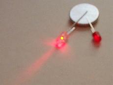
The first order of business is picking out your LEDs. They come in every color of the rainbow (red, green, blue, and yellow). They also come in many more exotic colors like purple and orange. The voltage that the LED draws is related to it's color. The green, red, and yellow LEDs are usually around 1.8V, blue is more like 3.7V, and white 4.0V. In addition to a variety of colors there are multitudes of sizes. This is a case where size truly doesn't matter. What matters is the amount of light that the "bulb" puts out. This is measured in luminescence or mcd. The larger the number the brighter the output. Also there are narrow beam and wide beam LEDs and lastly there are even blinking LEDs. Generally what you will want is a small LED that is very bright (500+mcd). The rest is up to your personal taste. Below is a picture showing the light difference between two red LEDs. The brighter one on the left has an output of 470mcd. Note that an increase in brightness doesn't increase the current draw.
Basic Test Frame
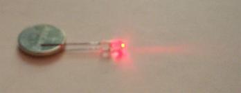
Now that we know a little about these pint size gems lets hook up the most basic of systems. This is not elegant, but works for trials and temporarily lighting a plane. All you need is an LED and a small 3 volt button style battery like those for hearing aids or watches. The LED has a positive and a negative terminal. Hooking it up backwards doesn't harm it, but you don't get any light. Of the two leads on an LED one is shorter than the other. It is the negative lead. Sandwich the battery between the leads as shown in the picture below.
You can then tape the combined unit onto the plane. This is also helpful when working on the placement of the LEDs before putting them on permanently. If you put an LED on the wing tip facing back at the plane it will light up the wing and fuse. If you place it facing out it will keep the plane dark, but provide a pinpoint of light in the night sky. You can play around with this type of temporary setup until you get the effect you are looking for. To turn off the light when not in use either separate the battery from LED or break the contact by sliding a piece of paper between the battery and one of the LED leads.
Serial or Parallel
If you are going to go with a permanent installation using a
larger battery you have two wiring arrangements to choose from. You wire
the LEDs in parallel, i.e. running each back to the power source independently
of one another. In this arrangement you will probably need to lower the
power going to the LED or you will burn it out. To figure this use the
formula Voltage (V)=Current (I)*Resistance (R) or V=IR. This same formulas
can be expressed as R=V/I to figure the needed resistance.
Example: If the you are running a 6 cell nicad pack each cell is 1.2 volts so
the pack total is 6*1.2 or 7.2. You will also need to know the voltage
used by the LED. For this example we will use a 4.0 volt white LED.
Next the current LED is rated for is needed. If you don't know the LEDs
rating .02amps is a good guess. So R=(7.2-4.0)/.02 or 160 ohms. LEDs
can actually be abused so a resistor with a rating greater than 140 ohms should
would work.
The other arrangement is to run the LEDs in serial, i.e. daisy chained off one
another. In this arrangement you run the risk of the old Christmas light
problem that if one goes out they all go out. It however will allow you
avoid the use of resistors. To do this simply add the number of LEDs until
the voltage they use is greater than or equal to the pack voltage. In the
above example adding 2 4.0 volt white LEDs in serial gives the following
R=(7.2-4.0-4.0)/(.02*2) or -20 ohms for resistance needed. A good
example of this is the above test bed. By using a single 3 volt cell with
a single LED the needed resistance is basically zero.
Power Source
To conserve weight the most common power source is to
"steal" from the flight pack instead of using a dedicated power
source. This can be done by tapping into the ESC or using the positive and
negative terminals on an unused receiver channel.
Light Placement
If you are looking for an accurate light scheme, airplane light positions are arranged similar to those of boats and ships. A red light is positioned on the left/port wingtip (when sitting in pilot seat), a green light on the right/starboard wingtip, and a white light on the tail. This arrangement is used for full scale pilots to be able to see other planes and determine the other planes orientation to them. This also works well for the RC pilot watching his plane from the ground.
If both a red and green light of the airplane are observed, the airplane is flying in a general direction toward or away from the pilot. If the red light is on the right the plane is coming toward you. If only a red light is seen or the red light is closer than the green light, the airplane is traveling from right to left. On the other hand, if only a green light is observed, the airplane is traveling from left to right. Note this reverses if you are flying inverted! Also real planes have bright white lights on the belly facing forward for landings.
Real Life Example
I have attached two LED's to the wing tips of a GWS cub.
Each wing tip has a yellow LED pointed in towards the fuselage and then a Red or
Green pointed out. They are both wired in serial. On the
yellow/green side no resistor is needed, but on the yellow/red side I have used
a 100 ohm resistor although I'm sure 60 would have been sufficient I didn't have
any on hand. I fried two LED's before I figured out that the difference
between the green and red LED's voltage was enough to require the
resistor. It's a good reminder to do the math before you start to
build. The wire used is from a IDE computer cable, I get 4 feet at a
surplus store for $1. It is light and flat and works well.
The yellow provides general illumination while the colors give the pilot the
planes orientation. I have not yet flown it at night due to the current
weather conditions. Here are some pictures.
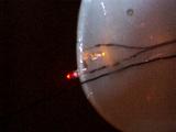
In the picture on the left you can see the wires running to the LED
terminals. The wire on the bottom is the antenna wire.
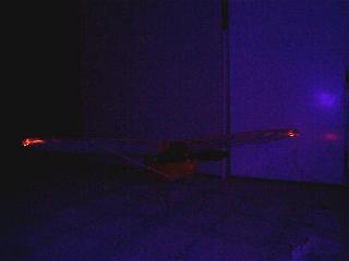
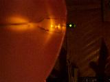
The picture above was taken in low light with purple Zagi tape covering the flash. This is why the whole picture has a bluish tint to it. It does however show the plane and the lighting on the underside of the wing.