Minnesota Area R/C Electric Flight Enthusiasts (MARCEE)
ELECTRIC 4 Star 40
Kit: Sig 4 Star 40
Electric Conversion By Ron Fikes
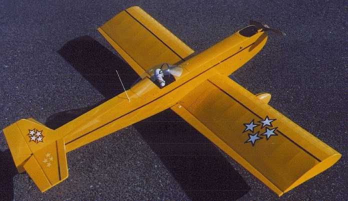
This is a conversion article of a Sig 4 Star 40 kit from gas to electric power. It was an excellent kit - everything fit and the materials were of good quality. I used a Sport Astro 25, stock gearbox, 14 cell 1400 mah battery pack, 12X8 Master Airscrew Electric wood prop (these have become sort of standard with our flyers for gear drives). I used a Futaba 4 channel AM radio and Astro 210 speed control. The RTF weight is 5 pound 3 ounces.
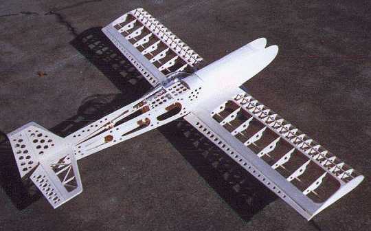
First secret - DRILL HOLES IN EVERYTHING! I drilled 471 holes in mine. I don't think it saved much weight but it sure kept me busy at the drill press. The best bit I found for clean holes is a Stanley "Power bore ". This bit works best when hole drilled 1/2 from one side, then piece flipped and the hole finished from the other side. There is a centering point on the bit so it cuts clean. You can take out most of the light ply with the hole drill because the wood is 'over' strong and the idea is to save weight.
On the wing, I used one Futaba 3101 servo on each side (bottom), and the rest was as per kit(I drilled holes in the ailerons). On the stab I cut out the center and installed square cross pieces and drilled holes in the elevators. I cut a little off the top of rudder and added a dorsal fin (drilled out) that ran up to the back of the canopy. I installed a Dubro tail wheel assembly at the rear of the fuselage (fastening the tail wheel to the rudder is a NO-NO!)
The fuselage was built like the plans except for ; leave out the lite-ply fuse doublers in the nose, use only one layer of the firewall with a large hole in it for wires and cooling, leave out the lite-ply tank floor (make up one to take it's place that goes from the firewall to about former IP, drilled out and covered with Velcro. This is where your battery pack goes). Don't use the 3/32" die cut fuselage top deck. Make up a top deck from a soft balsa block that goes from the firewall to F3. This will be your battery access hatch - cut-off right in front of canopy and about an inch from the firewall. Glue these two pieces to the top, the rest is your hatch. You will have to cutaway the top of F2 to accommodate the battery pack. The two servos for rudder/elevator were mounted in the fuse between F3 and F4, with an access hatch on the bottom (there is already a hole there). Leave the rearmost oval hole in the bottom of the fuse uncovered for air outlet.
The canopy is fastened with #2 button head screws. I used the stock landing gear with Dave Brown foam wheels (sanded to pointed shape). The pants are Sig 7 1/8"units. Now to the meat, I mean motor mounting. I installed (epoxied) a bass (3/8" sq) beam on each side of the cowl cheeks (with the appropriate down thrust, just what the plans showed), made up a 1/8" aircraft plywood plate to go from side to side and long enough to reach the nose. The seams should align the plate so the motor shaft is in line with the plans shaft. This plate is screwed to the beams with 4 #4 button head screws. Put two triangle balsa strips on this ply piece to keep the motor lined up, then make two brass strips to wrap around the motor, and bolt to the ply plate with 2/56 bolts (ala Bob Kopski, Model Aviation magazine). This makes thrust changes painless and motor changes, too.
I use Dean's base loaded antennas on all my planes, vertical position (sticking up right at the rear of the canopy) is best but built into the wing or fuse is good, too. Seems to be good at range, also - I've never lost one for range problems. The covering is Monokote and the beautiful pilot is 'Na' from the Graupner catalog.
This was one sweet flying plane, pretty aerobatic - but if you really want it to be a screamer, you should go to a 40 Cobalt. Flyers at KRC have built this with a 40, but I like to fly on the wings, not the prop, so...
A picture of my 4Star is on the November page, '97 Sig calendar.
Email: Ron Fikes